Pico TC-08 USB Interface Part 1
Pico TC-08 USB Interface
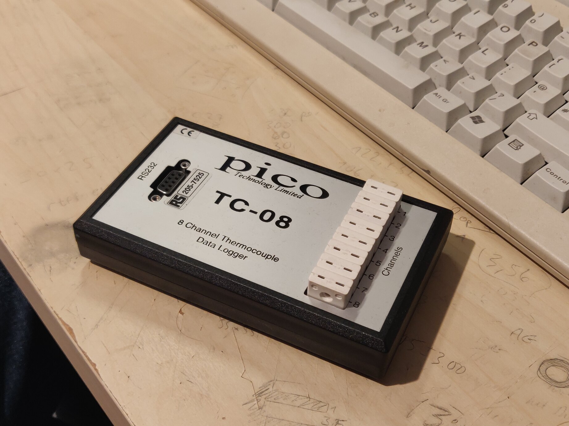
After acquiring this lovely example of an old Pico TC-08 thermocouple data logger (complete with all 8 T-type thermocouples!) I quickly discovered using the thing wasn’t going to be as easy as I had initially assumed…
Quick Links
A Cheap Thermocouple Solution
Originally priced at about £150, I managed to score mine for just over 20 quid, with others readily available for around £30/40. Not too shabby considering the new USB version is over £200! (Top quality kit though).
The unit even came with an RS232-USB adaptor, which was handy since the one I already had used the female connector whilst the unit required the mating male connector. A minor inconvenience a few bodge wires cant sort out.
Ancient Software
Being a fairly old product of theirs, the downloads were found behind a few dusty cardboard boxes within the filing cabinet of Discontinued Products. By discontinued, they simple mean that the current version of the PicoLog software does not support the drivers for this device, and as such the latest compatible version was 5.25.3 from 2016 (dubious dating on this website).
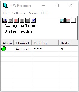
Apart from requiring a microscope to operate, the software is actually quite simple to use. Basically the same as their modern software package but without the friendly colours. The only counterintiutive thing encountered may be that the setting of how long you wish to record, and how often is found under Sampling and not Recording, but this is a minor issue.
Standard Adaptors Don’t Work!
As you may guess, the included adaptor didn’t work. Neither did my own, prompting an increasing familiarity with the following message.
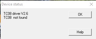
The reason for this comes from the fact that the power for the TC-08 comes straight from the CTS and RTS lines on the RS232 port. It’s a fair assumptino that most modern drivers are unable to supply this power since they’re likely based around an FTDI FT232R which is rated to only supply up to 24mA from those pins.
On second thoughts I presume most adaptors must have some kind of level convertor in there, so presumably that’s doing the current throttling? Either that or it’s not complying with the drivers.

I had bodged together a setup to provide the required +/- >7V rails specified, and measured (vaguely) the current draw to be around 10mA on the +VE rail and -30mA on the -VE rail at +/- 10V.
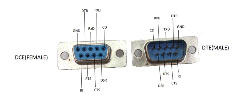
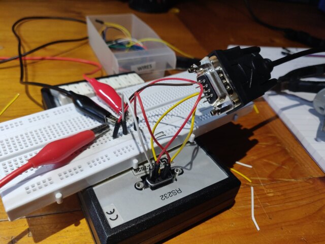
Since externally supplying the power through the relevant pins was a success, I decided it was time for a more usable solution. Time for a board layout perhaps.