LED Matrix: Part 1

Quick Links
A friend of mine was going about printing a replica of Thomas from Daft Punk’s helmet. Natural, he wanted to fill it with nice shiny LEDs in the standard matrix form as you see on the interwebs. Now, despite this having been done before, the only ones we’ve seen were either using RGB addressable LEDs, or were single colour and could be done with standard driver. This isn’t what he wanted. He was after an RGB display, but at a much lower cost than achievable with addressable RGB LEDs. (Can’t blame him when you’ve gotta buy 320 of the things at maybe a quid each!).
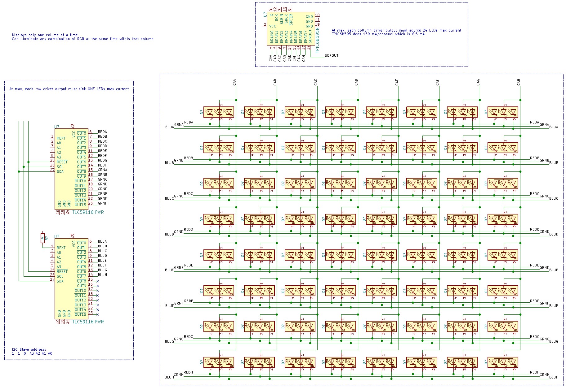
After a lengthy, tangentful call on discord, we came up with what you see above.
Operation Principle
The principle of the scanning matrix is very simple, and details of any precise timings will be kept until I discover what they actually are.
In this instance, you can think of each of the R, G, and B segments of each RGB LED to be a separate row. This should ease understanding.
- Power is applied to each column in turn by shifting a bit to the appropriate position in the column shift register.
- The row drivers set their output to be high or low as appropriate for the LEDs in that column.
- Hence only one column lights it’s LEDs at any one time.
In this instance, the row drivers used are 16 channel PWM LED drivers, allowing for setting the brightness of each LED individually, as well as providing global dimming control. Very handy.
How many LEDs?!
So the original plan is for a 40x8 display totalling 320 LEDs. All RGB of course, so in working terms it’s actually a 40x24 grid of LEDs. The hope is to treat them as 5 blocks of 8x8 arranged horizontally which works nicely and allows pairing of each block with a single solumn driver, whilst the row drivers are common across the whole display. When it comes to programming them, it should be relatively straightforward and not require too much fiddling with mapping co-ordinates to driver positions.
In application (images to come) they curve round a fairly tight bend, and if possible, need to allow some space between them to allow the person to see out of the visor.
I’m unsure what LEDs have been chosen but it was a fair assumption that they’d want to be drawing somewhere around 5-10 mA since they just need to be seen, not project or illuminate anything, which necessitated the power shift register as a column driver.