Tolerancing and Desgning Printed Parts for Fitment

Tolerancing - Quantified compromises if you ask me… Lovely!
External Profiles
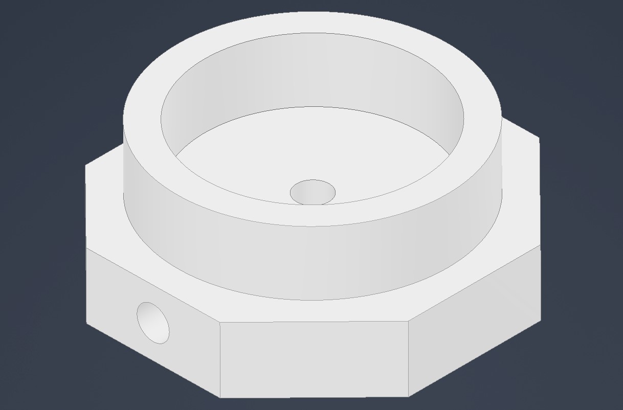
This tends to vary somewhat based on the direction of the print relative to the X-Y axes of the printer.
On my test print I measured across opposite faces -0.05mm to +0.08.
So that’s a tolerance of +0.08/-0.05mm which is quite acceptable.
The smaller dimensions were in the directions of the machine X-Y axes, whilst the large measurements were at 45° to the axes. I presume this is some minor artifact due to the stepping not being perfect when doing compound movements involving two axes.
The upper (round) part of my test print measured down -0.15mm all around and was very consistent. Not sure why it’s different, perhaps structure is different due to the lack of infill on these layers. Less expansion perhaps?..
Internal profiles
Again, errors in the X-Y axes were -0.45 to -0.40. At 45° to this it was near identical. As a rule, all prints I’ve ever made tend to be slightly undersized on internal profiles and pretty much bang on with external profiles.
Holes
I suppose the big round bit in the top of my print is a hole? Either way it has the same tolerance as one. As best as I can measure the 3mm holes in the print I read off somewhere between -0.48 and -0.30.
Any rules of thumb about internal profiles clearly also extend down to small holes.
Personally I’d drill out any holes if I intended to actually put anything through them. If they’re too large to drill then I’d obviously have to compensate with the dimensions of the model input.
I’ve not tried compensating with small holes because the bottom layer generally squishes out increasing these errors even further, so drilling out is generally done for that anyways.
Z Dimensional Error
At the time of writing, my printer has a tendency to lose about 0.45 to 0.40 mm off the bottom of the print. Sort of squishing some of the lower layers. I generally just extrude an extra 0.45 in the model to account for this but am in the process of looking for a cause and solution.
Bar the above mentioned error, Z axis is generally alright at around +/-0.01 for dimensions not involving the bottom layer. If you include the bottom layer then expect some worse measurements.
Small Note
I should quickly note: yes this is a sample size of one in terms of prints and printers, but I have observed very similar errors in multiple prints from an Ultimaker 2 Extended+ which I’ve been using for something like 4 years now.
Neither printer has ever had its axes steps calibrated (although I recently did the extruder calibration on my Ender 3 V2).
Designing for Fit
If we were dealing with machined aluminium parts you might dust off your copy of machinery’s handbook, cringe at how much you spent on it, remember it’s an amazing piece of reference text worth every penny, and then flip to page 683, and spend hours working out what clearance you need relative to the tolerance obtained with your printer’s accuracy…
What I present here is not definitive, but has served me near infallably as some good rules of thumb for ensuring printed parts fit together properly once printed. Of course, there are some exceptions, but nothing’s perfect.
These apply generally to any profile you can think of. So far I’ve not had a problem, but have found that depending on the wind direction and the alignment of Neptune, nudging these offsets up or down by between 0.01 and 0.03 (rarely) can help get that perfect fit.
Types of Fit
I suppose I can put the desired possible fits into about 3 categories:
- Sloppy fit
- Slight interference fit
- Press fit
Sloppy fit - External Dims -0.30
Not quite hot-dog down a hallway level, but enough to jimmy about for aligning a hole. Expect this type of fit to be somewhat disappointing and can be compared roughly to a machined very loose sliding fit.
Slight Interference Fit (Perfect) - External Dims -0.18
Unlikely to be shaken apart unless it’s got some mass on it. Generally the most desireable fit. Also perfectly suitable for where one part passes through enough like a hinge or summin’. Gives that nice “klop” sound as you press it together.
Press Fit - External Dims -0.14
Good for pressing in bearings, lids, or press fitting parts together. Not so horribly tight it wouldn’t work loose so don’t use this for structural stuff. Use glue on this joint if you really need it. Also, due to the tight fit between the parts, any artifacts in the print cause significant errors in alignment here.
3D Printing doesn’t always give you much room to work around these tolerances since they somewhat rely on imperfections in the printed surface due to extrusions inconsistencies, and rough interpolation of curved surfaces.
Sorry there’s so many words here. Statistics doesn’t normally come very graphically…