Tolerancing 3D Printed Parts: Revised Edition
Preamble…
These are some general rules of thumb for designing parts for 3d printing to assemble together. They are the general rules I’ve been using myself now for many years across multiple Ultimaker and Ender series printers. It’s a fair assumption they should work for other printers of reasonable quality.
Causes
There are generally two causes for prints ending up with non-ideal dimensions:
- Slicing
- Printer Errors
Slicing
Due to the fact that a printers axes move in steps, its is necessary to produce instructions that move in a series of straight lines, effectively interpolating between points on any curves to produces a best estimate of it.
Printer Errors
Not all printers are created equally. Any slop in the X-Y axes will lead to positional errors in extruded parts, as well as errors in the extruder calibrations leading to over or under extruded parts, which again are errors that affect the dimensions of the prints (often in very unexpected ways). Slop in the Z axis of the print can often result in the lower walls of a print flaring out, effectively resulting in a larger overall dimension of the part at the bottom, compared with the upper layers.
X, Y, and Z step calibrations are generally quite good from the factory, but could be worth checking if things aren’t fitting together with the clearances described in the following paragraphs. I personally had more issues with over and under-extrusion causing terrible positional errors and giving terrible variations on the first layer, and calibrating my extruder solved this error. This was experienced on multiple printers encountered so it would be a reasonable first check if errors are unacceptable only on the bottom printed layers.
Either way, dimensional errors are likely to be the greatest on the very bottom, and very top layers (in the case of a rather tall print). Getting this interface right, as always, is the hardest but most important part to consistent fitments of printed parts.
General Expected Tolerancing
On a good quality printer (SLA or something like an Ultimaker) you might expect the majority of prints to come out with tolerances in the realms of 0.1mm. Ender 3 printers tend to come in slightly above that but not exceeding 0.15mm and they can be set up to achieve under 0.1mm tolerance if desired through proper belt tensioning and adjusting the eccentric nuts appropriately.
SLA has the potential for finer general tolerances but I have no experience with such printers. FDM based printers will generally happily achieve <0.2mm tolerances on average, but expect that the worse the machine, and how badly it is set up/abused, then this average acceptable tolerance will have a larger variance. I.E. In a terrible case, printing the same part twice might result in measurements of 2mm (ideal result) followed by a measurement of 2.3mm (not so ideal).
If you’re trying to profile what a printer can achieve then it’s a fair assumption that it will always be printing either too large, or too small, in a given direction on a given feature.
Externally Fitting Parts
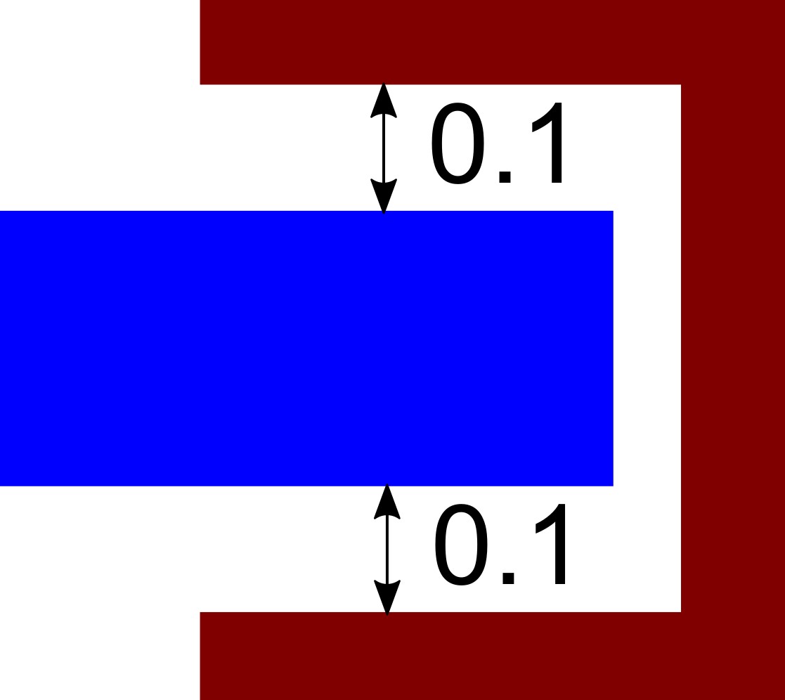
These are the most generic clearances I can provide and the results of which vary the most in my experience from design to design. Take the 0.1mm clearance against each face to be the average, and increase for a very loose fit, and decrease for a tighter fit.
Holes Generalised
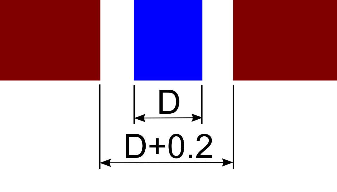
Adding around 0.2mm to a hole diameter should result in a printed hole which is pretty close to the desired size. If you want a clearance hole for an M2.5 screw (typically 2.6mm) then you’d model the hole at 2.8mm diameter. Reduce this clearance and run a drill through the hole if you’re looking for a particularly closely fitting hole.
Holes In The X-Y Axes
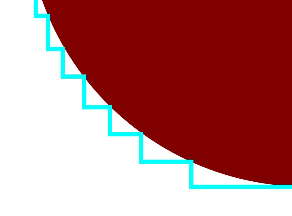
From experience I can say that these holes tend to end up a little closer to the desired size than vertically printed holes. The image above illustrates why I believe this happens, although I have not tested this theory. However, expect to have to run a drill through the hole to remove the final bits of support if used, else to clear the top edge of the hole which would likely end up sagging a little.
Holes In The Z Axis
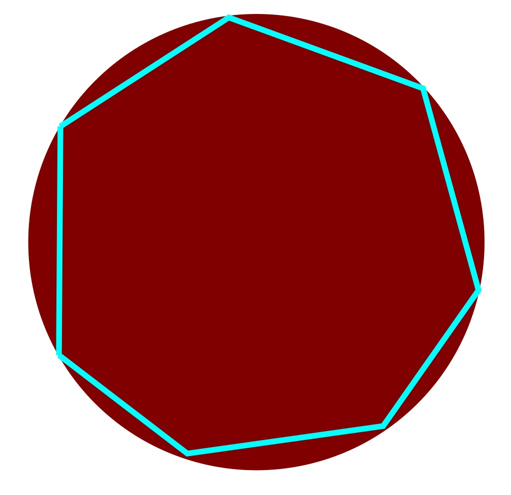
These holes are more desirable to print, but are more subject to any first layer problems you might be having. Again, expect running a drill through it should clear most of this up, hence the same requirements for clearance as the horizontally printed holes. Using a 0.5mm chamfer on the edge where the hole meets the build plate can somewhat alleviate these problems.
Threads
At some point you’ll want to be using screws to fasten things together. Just don’t bother attempting to print threads as part of the model.
Tapping the threads after printing is really just a given here.
External Threads
You’ll need to find out the major diameter of the thread and then have your print that diameter. With respect to threading the part afterwards, any old die’ll do. Sometimes spinning the part with some fine sandpaper on it to clear up imperfections helps a little with the tapping process, and putting a 0.5 or 1mm chamfer on the leading edge of the thread helps considerably in getting a good start (as it does with most materials).
Internal Threads
CAD programs modelled threads will generally end up as the core diameter of the thread, which as discussed earlier will result in a print of marginally smaller diameter than required. To avoid this issue, either print at this size and then drill out with the appropriate tapping drill, and then tap out the thread. Or, as I personally do, print the hole you want tapped at the size designation of the thread. I.E. if you want an M2 thread, model a 2mm hole, if you want an M4 thread, model a 4mm hole. This doesn’t work that great for particularly large diameter threads, but works absolutely fine for the smaller ones (perhaps a bit sloppy on occasion though so could possibly try printing at designation size minus 0.1 - so 1.9 and 3.9 in the above examples.)
If possible, use a spiral fluted tap. Plastics are very soft and require alot more swarf extraction to avoid binding or destroying threads whilst you’re tapping. Generally a spiral fluted “second” or “plug” tap is ideal for most plastics, and then use a bottoming tap if required in a blind hole (although expect clogging issues tapping blind holes, you’ll likely need to remove the tap and clear the flutes every time it feels tight to avoid ripping your thread out, although this is a general rule for any hole). Straight taps will work fine for short threads, but if you’re going any reasonably depth (<5mm perhaps) then you’ll thank me later if you use a spiral flute tap.
Lids
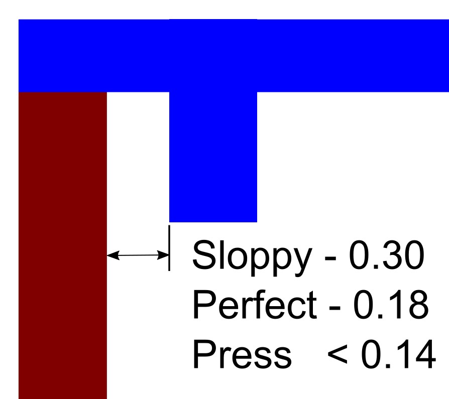
Obviously this all depends on the exact geometry of the lid you have, and square corners can cause some issues with overextrusion at the corner so are best avoided (just use a 0.5mm rad at least and this becomes a non-issue). Generally speaking these numbers are good for any shape lid though.
Sloppy Fit - 0.30mm
Guaranteed to fit, and will allow loads of room for aligning holes and other things. I really do mean loads of room…
Perfect Fit - 0.18mm
The clearance you’ll want to be using 99% of the time. Slides right into place with no observable slop. This is a printer specific thing, so once you’ve fiddled the value (try +/- 0.03) for the perfect fit, you can continue using this value forever…
Press Fit - 0.14mm
Not horribly tight, but definitely isn’t coming off if you wave the box around. Makes a nice klop sound when you put it together. Again, you may have to fiddle the exact clearance for what you’re trying to achieve but all prints I’ve used are around this value.