Pico TC-08 USB Interface Part 2
Pico TC-08 USB Interface

Schematic
In order to provide the actual USB interface a FT232RL was chosen since it was a relatively commonly used part. To make the interface of the required voltage for RS232 an ADM213E was used. This chip includes it’s own charge pump which, although maybe unnecessary due to the fact those rails are being provided elsewhere on the board, was nice and easy.
The chip was by no means ideal, since I only needed 1 input and 1 output, and I’m pretty sure it’s not obsolete, but it was the only chip I could find that was in stock. Since I only needed one board in reality it didn’t quite matter.
The DC-DC convertor used was an IAO512D which, again, was chosen because it was available, was quite cheap, and met the spec (a common theme for all these parts really).

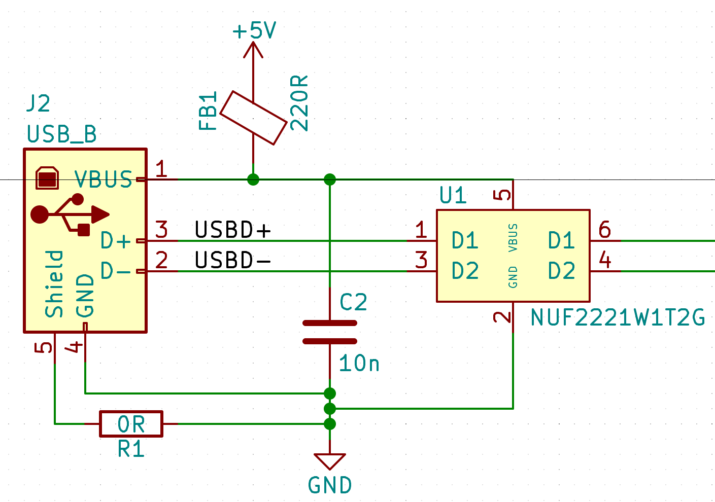
A USB B connector was used since they tend to be a little more robust than other connectors, and since the board otherwise receives no mechanical support besides mounting on the D-SUB connector, this should ensure it lasts a little longer than hanging off a little mini or micro USB connector.
ESD protection is provided with a NUF2221W1 and the connector shell is not connected directly to ground. A resistor is there just in case it’s decided it needed to be, but generally I was recommended by a friend to assume that in his experience grounding the shell causes more problems than it solves (something to do with cheapo USB drivers waggling the USB shield around at non-ground voltages).
Other than the above, the rest of the components came straight from the datasheet reference designs since those guys know what they’re doing.
Board

Overall the board was quite simple to layout.
The board outline was decided from drawing out the footprint of the TC-08 on the dwgs layer and using it as a visual aid.
Test points were provided for testing of the +/-12V rails from convertor since I had a sneaking suspicion that I might exceed the maximum draw from them, but this didn’t prove to be the case.
After building up most of the board, I tested the output of the convertor to see if it was within the acceptable range. It measured around +/-14V which considering I wasn’t meeting the minimum load spec was reasonable so assembly was continued.
Bar a couple of dodgey joints, this was one of those rare occasions where the board just worked. Initially it didn’t since a few smt joints were lacking some solder but otherwise it was quite good.
Files
If for some reason you decided to score an old TC-08 (RS232) of your own and want a board, go ahead:
Enjoy.
